THS Engineering
Mechanical & Electro-Mechanical Systems
| Home |
| Consulting |
| Products |
| Surplus |
| Projects |
| Resources |
| Contact THS |
A3977 Microstepping Stepper Motor Driver Prototype PCB
| Update 2/6/03: Prototype boards are Sold-out! Improved design (THSTEP25) is now in stock. Visit our Products Page to order online. |
This bipolar chopper step motor driver prototype board is designed around the Allegro 3977 chip. Each board drives one axis and is 2.5" X 1.9" in size. It provides for the minimum circuit requirements to get the A3977SED chip up and running. This product is intended for the experienced electronics hobbyist. It may require some experimenting and modification to work with your particular setup. This is NOT a complete kit - Bare PCB only!
You must provide your own A3977SED, passive components, solder, tools, stepper motor, DC power supply, fan and step & direction signal source. Note that SMT soldering techniques are required for the A3977 IC. (see Resources below)
Specifications:
- Drive type: 2 Phase Bipolar Chopper Microstepping
- Absolute Max Output Current: 2.5 Amps
- Absolute Max Input Voltage: 35 Volts
- Step options: Full, Half, 1/4 and 1/8 Microstepping jumper selectable
- Digital Inputs: Step, Direction, Enable
- Digital Outputs: Home
- Chipset: Allegro A3977SED (44PLCC SMT package)
- Footprint: 1.9" X 2.5"
Offsite Resources:
Check the A3977 page on Allegro's Website where you'll find the .pdf Datasheet. Some useful information can also be learned from the A3977SED Product Evaluation Kit
Although the A3977 can be soldered using a small soldering iron, a very good tutorial on SMT soldering in a toaster oven can be found in this article by Kenneth Maxon.
Detailed PCB Info:
Please start by carefully reading Allegro's Datasheet. The following list is parallel to the datasheet's "Functional Description" section and describes how this PCB provides for each requirement.
- Reset Input (RESET) - Hard-wired logic HIGH (inactive)
- Home Output (HOME) - Brought directly to terminal block.
- Step Input (STEP) - Brought directly to terminal block (no onboard pull up/down)
- Microstep Select (MS1 and MS2) - Jumpers provided to tie each HIGH or LOW
- Direction Input (DIR) - Brought directly to terminal block (no onboard pull up/down)
- Internal PWM Current Control - Itrip reference voltage is provide by a trimpot w/ decoupling capacitor.
- Fixed Off-Time and RC Blanking - two 30k resistors and two .001uF capacitors provided (substitute appropriate values for your application)
- Charge Pump. (CP1 and CP2), Vcp and Vreg - three .22uF caps provided.
- Enable Input (ENABLE) - Brought directly to terminal block (no onboard pull up/down)
- Sleep Mode (SLEEP) - Hard-wired logic HIGH (inactive)
- Percent Fast Decay Input (PFD) - PFD reference voltage is provide by a voltage divider w/ decoupling capacitor.
- Synchronous Rectification (SR) - Hard-wired logic LOW (active)
- Layout and Grounding - Large ground plane provided for low impedance and heat dissipation. Electrolytic capacitor provided for VBB decoupling
- Current Sensing - Two .2 Ohm low-inductance "wire element" type resistors provided. Two .1uF capacitors provide filtering
Logic Supply: A 5 volt DC logic supply is obtained from the stepper supply via the LM317 voltage regulator provided onboard. This regulator was chosen over a fixed regulator because it can tolerate the full rated 35V input of the A3977. Alternately, an external 5 volt supply can be connected to the "5V" pin and the LM317 omitted. Note that an external supply must share a common ground with the stepper supply and watch out for ground loops. A .1uF capacitor near the A3977's logic supply input pin provides decoupling.
| Schematic: |
|---|
| Click for full size image |
|
| Parts Placement and Pinout: | |||||||||||||||||||||||||
|---|---|---|---|---|---|---|---|---|---|---|---|---|---|---|---|---|---|---|---|---|---|---|---|---|---|
| 
| ||||||||||||||||||||||||
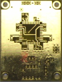
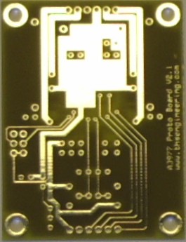
Final PCB Layout: |
|
| Top | Bottom |
 |
 |
 |
 |
| Parts List: | |||
|---|---|---|---|
| Description | Source | Source P/N | Qty. |
| Allegro A3977SED | Arrow | A3977SED | 1 |
| .2 Ohm I Sense Resistor | Digi-Key | 13FR200-ND | 2 |
| 47uF cap 35V Axial | Digi-Key | TBD | 1 |
| .1" 6 pos. Terminal Blk. (opt.) | Digi-Key | 277-1277-ND | 2 |
| Bourns 3266W-1-103 10k pot | Digi-Key | 3266W-103-ND | 2 |
| *OR* 10k Micro Pot | RadioShack | 271-282 | 2 |
| .025 pin header 2x3 | Digi-Key | TBD | 1 |
| Shorting Jumper | Digi-Key | TBD | 2 |
| LM317LZ adj. V reg TO-92 | Digi-Key | LM317LZ-ND | 1 |
| .1uF Ceramic Cap | Digi-Key | 399-2155-ND | 6 |
| .22uF Ceramic Cap | Digi-Key | 399-2157-ND | 3 |
| .001uF (1000pF) Ceramic Cap | Digi-Key | 399-1941-ND | 2 |
| 30k 1/4 Watt Resistor | Digi-Key | TBD | 2 |
| 1k 1/4 Watt Resistor | Digi-Key | TBD | 1 |
| 330 Ohm 1/4 Watt Resistor | Digi-Key | TBD | 1 |
| A3977 Prototype PCB | THS Eng. | A3977Proto | 1 |
| Notes: All ceramic caps are .1" lead spacing. Terminal blocks are optional and can be replaced by .025" pin headers or wires soldered directly to the PCB. The Bourns multi-turn pots are nice but expensive so an alternative is the single-turn RadioShack trimpots or even fixed resistors. | |||
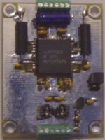
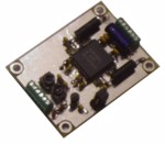
| Assembled PCB |
Assembly Tips:
Make the A3977 the first component that you solder to the board. This is contrary to the usual practice, but that's the only practical way to do it.
We recommend the oven reflow process over the soldering iron method. Future Active may have a better price on the solder paste than Digikey.
If you don't have the solder paste but you do have a liquid flux you can use an iron to tin the pads, then flux the leads and the pads well, tack one lead in place and put it in the oven.
Next bend and trim the .2 ohm resistors, but don't solder them in yet. Solder a piece of the leftover lead wire into each of the high-current vias. (4 stepper outputs and 2 Vbb connections)
Solder all the ceramic caps next. Then the resistors, voltage regulator, pots, etc.
The electrolytic cap may be a tight fit.
When powering up for the first time, tie the enable input high. This disables the stepper outputs. Check the 5V supply voltage is correct, check for hot components, etc. Adjust the current set pot to the desired voltage according to the datasheet.
Don't leave any inputs unconnected. The HOME output may be left unconnected, however.
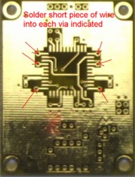
| Solder a short piece of solid wire into each high-current via. |